![]() Get the latest Technical Tips and information from our Technologies Team on prepress, plate-making and print. Our team is comprised of a group of diverse individuals who have strong backgrounds in design, color, plate-making, proofing and press applications. If you have any question that you can’t find the answer to, contact us directly at techsupport@andvre.com.
Get the latest Technical Tips and information from our Technologies Team on prepress, plate-making and print. Our team is comprised of a group of diverse individuals who have strong backgrounds in design, color, plate-making, proofing and press applications. If you have any question that you can’t find the answer to, contact us directly at techsupport@andvre.com.
Tech Tip 1- Water-wash Platemaking Guidelines
1. When should a customer check the caliper or thickness of the plate?
- The customer should verify the material gauge for each new batch of material before processing, as well as measuring every plate after washout.
2. What process is used to determine the proper plate relief?
- A back-exposure step-test, with the micrometer for verifying thickness.
- Ideal relief on digital plates is 0.018” – 0.022”.
3. What facility components need to be inspected prior to a water-wash equipment installation?
- Water Hardness: pull a sample and ship to Roy Willitzer in Bryan for evaluation. If the water is too hard, a water-softener may be required.
- Optimal Power Supply: See Pre-installation guide by AV Engineering team for full specifications.
- Can the Equipment easily fit through doors & pass by other equipment to be placed?
- Optimal Water Supply.
- Sink for Rinsing (Recommended).
4. What is the proper pH range of the water-wash water?
- Above 9.8. If pH drops below 9.8, soap must be added.
- Soaps should be verified & approved by AV Technologies & Engineering Teams.
5. How often should the pH of the water be checked by the operator?
- Every 4 plates.
6. What are the possible effects from improper brush settings?
- Too shallow of a floor, brush marks on the floor, improper washout inconsistent brush wear.
7. What happens if a plate is over-washed?
- There is risk to removing small dots.
8. What happens if a plate is under-washed?
- There will be left-over polymer residue, inconsistent dot size, and inconsistent floors.
9. What is the proper drying temperature for Cosmolight?
- 140 degrees Fahrenheit (at 150 degrees the polyester back could begin to distort).
- Be sure to measure with a thermometer at both sides (left and right) of the dryer drawers./li>
10. What do you do with the Cosmolight waste-water when draining/cleaning the Whirl-away or Cosmolight tank?
- Do not put the waste water down the drain! First, check with local water regulations and have the sample tested. Most Cosmolight customers should be draining the wastewater into a plastic-bag lined 5 gallon bucket; then adding a solidifying agent. Once the water has turned to a solid, the bag can be thrown in the trash.
11. What is the proper temperature range of the Cosmolight water?
- 105-110 degrees Fahrenheit.
Tech Tip 2- Viewing Conditions
Everybody wants a brighter white paper, but achieving those bright paper whites can be difficult and costly. In come OBA’s or optical brightening agents. These are additives to paper that fluoresce in UV light, appearing white to the human eye, and are a cost effective way to make paper appear whiter. Because of this, the use of these additives has increased greatly, along with some challenges for color matching. The amount the OBA’s fluoresce depends on how much UV content is in the light source where they are being viewed, however previous standards for viewing conditions and measuring devices didn’t define the amount of UV content in the light sources. This can lead to colors appearing different in different light booths, depending on the UV content in the bulbs. In 2009 ISO published ISO Standard 3664: Graphic technology and photography Viewing Conditions, which outlines the conditions for viewing and comparing proofs to a print, including a more specific definition of the amount of UV content in the bulbs. Here is where we are today:
Graphic technology and photography Viewing Conditions
- The viewing area should be a neutral gray.
- Bright colors, extraneous light, and anything else that may affect the viewing should be removed from the area.
- The use of a light booth can help as they are generally painted neutral tones and block distractions in the room.
- The light source should be CIE Illuminant D50 and be uniform across the viewing area.
- The images should be compared on either a black or white backing, similar to the conditions the profile data was measured on.
- The graphic arts industry usually uses white unless the print is 2-sided, then black should be used to reduce or eliminate the amount of image show-through.
- We recommend choosing a standard paper or tile to be used throughout the plant.
- The images should be viewed at an angle to reduce the glare.
If I already have a light booth, what does the new standard change for me?
- If you’ve replaced your bulbs in the last 2 years from a graphic arts source (not the local hardware store) then your bulbs are most likely compliant with the new standard.
- If you haven’t changed your bulbs in the last two years, you probably need to, regardless of the change in standard. They are most likely no longer conforming to the new standard or the old standard.
- If you print on film or on stock without OBA’s, this won’t change much for you. The added UV in the lamps has nothing to react to in your substrate and therefore color will appear the same.
- If you print on substrates with OBA’s you could start to see a difference between proofs and press samples that previously matched.
What to do if I have OBA’s?
You have two choices for comparing your proof and press sheet to view comparable results:
- Some light booth manufacturers have a filter for light booths that will filter out the UV, returning the light booths to the same state they were in pre the 2009 standard.
- This will create a visual match in the light booth, but will not meet the most recent standards.
- In order to get a match and comply with the latest standards, profiles will have to be recreated – printed then measured using the new M1 measuring light source standard that also includes a defined amount of UV content.
- This would comply with the latest standards and allow a proof to press match with this lighting condition.
Tech Tip 3- Best Practices: Plate Mounting
The plate mounting department is a critical area for ensuring good registration on press as well as long run- life of the plate. If plates are handled poorly during mounting, the result could be defects in print, registration problems, ink-transfer issues, and/or press down time due to plate lift or sleeve/cylinder failure. Please see our tips below for plate handling and mounting guidelines.
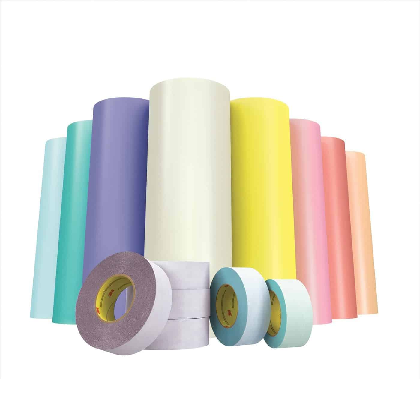
3M Mounting Tapes
Is checking bearings an important part of mounting when mounting direct to cylinder for a label press?
- Yes. A simple spin of the bearing can determine if it’s good or bad and can
prevent down time on press. Bearings that don’t spin freely should be greased or replaced if damaged.
Is it important to clean all grease and ink from cylinders?
- Yes. Grease or other contaminants can cause high spots or plate lift. It is always a good idea to clean with Isopropyl Alcohol or Acetate.
What is the main purpose for applying tape or hot-melt glue in the plate gap?
- To prevent solvents or inks from working their way between the plate and sticky back or sticky back and cylinder. This helps prevent plate lift.
Can a dull plate cutting blade contribute to plate lift?
- Yes. Instead of cutting, a dull blade will actual burst through, leaving a burred edge on the polyester side of the plate. This prevents good contact with the sticky back.
Would you clean a plate with a standard bristle brush?
- If using a brush to wipe or clean plates, the bristles need to be soft so dots are not damaged. A horse hair brush or a Pamarco Care Pad is preferred. Also, no woven fabrics – these will catch and shear off small dots.
Is it safe to clean photopolymer plates with basically any cleaner we find on the shelf?
- No. Many cleaners can have chemicals harmful to plates. Many cleaners contain solvents that may change the surface characteristics of the plate and therefore the print. Isopropyl Alcohol is generally recommended. However, always check with the plate manufacturer for the best/recommended plate cleaning solution.
Are Mag 44 markers and 3M’s primer 94 are two ways to increase the surface tension of a plate for increased adhesion plate to tape?
- Yes, these promote adhesion, but will not prevent solvents from penetrating the bond between tape and plate or tape and cylinder.
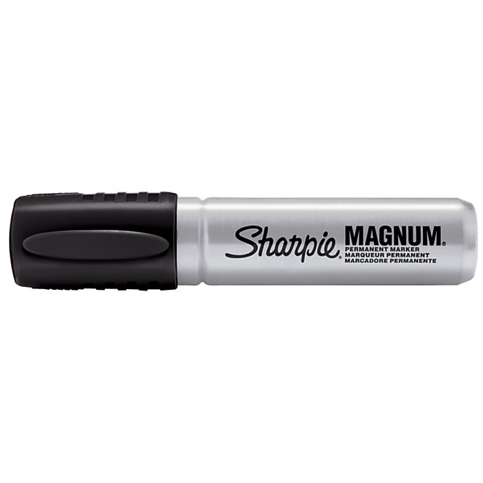
Sharpie Magnum marker
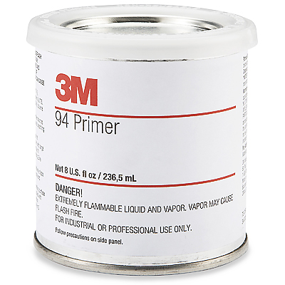
3M Primer 94
What’s the best tool for laying down a plate?
- In most cases a brayer, not your hand. However, there are many new devices with safety in mind where a brayer is no longer needed providing less wear and tear on operator’s hands and wrists.
Is an interleaf between plates helpful in storage?
- Yes. The foam interleafed between the plates from the manufacturer work best. Never store a plate print-surface to print-surface.
Can cornstarch or talc powder be used to deaden the adhesive properties of the tape in areas exposed?
- Yes. Many operators will remove that tape, however keeping tape along the length of the cylinder is a way to keep cylinders clean. The use of powder reduces the tackiness for easier handling.
Can hypodermic needles be used to get rid of air bubbles?
- As long as you are piercing through the floor of the plate.
What is the best location to line your cameras up to on the plate? Tail or middle?
- Middle. The easiest and most efficient way to get a plate mounted square is by starting in the middle of the plate.
Can rounded corner cuts prevent plate tear during de-mounting?
- Demounting a staggered-cut plate with 90 degree corners without tearing the plate is extremely difficult. It is recommended to round the internal corners to help reduce plate tear during demounting.
Can cracked sleeves be used with care to avoid blow-out, or cutting an employee?
- The best solution is to remove the damaged sleeve from production and repair or replace it from the OEM.
What is an easy way to work with sleeves with notches?
- Order the sleeves notched for both sides. A double notch can prevent mounting in the wrong rewind position.
Should you clean backs of plates with Isopropyl Alcohol or Acetate before use?
- Yes. If left dirty this can create high spots or plate lift. It is always a good idea to clean with Isopropyl Alcohol.
Do I need a maintenance program for mounting devices?
- Taking scheduled time to keep equipment in top running shape helps prevent downtime during critical times.
For additional information please email techteam@andvre.com
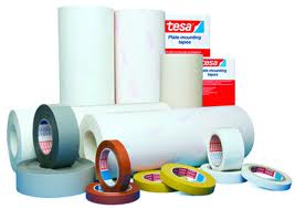
Tesa Mounting Tapes
Tech Tip 4- Utilizing the Xrite eXact 2
Many printers have densitometers and spectrophotometers in the prepress area or press room, but often don’t use them or use them to their full potential. This can be for any number of reasons, fear of measuring incorrectly, not understanding the proper order to take measurements, or where to find the function that is needed at that critical moment during a customer press check. (And what the number on the screen actually means!
This Tech Tip provides an overview of some of the most commonly needed measurement functions of the Xrite eXact spectrophotometer and how to quickly and easily use those functions. Also included at the end is a “Help!” section to guide the user to locations where more information and training are available.
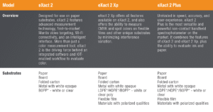
Determine the Version.
- There are multiple versions of the Xrite eXact 2, ranging from the basic densitometer, up to the latest XP version, designed especially for measuring on film substrates. Below shows a chart describing the most common functions and differences between each device.
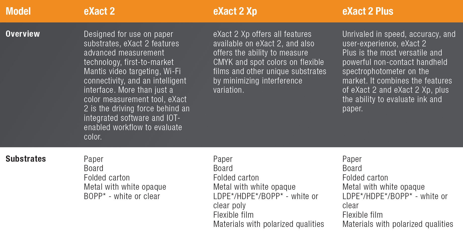
- Also listed below is a chart of the available aperture sizes. Selecting the right aperture at the time of purchase is important, as it is expensive to modify later.
Configuring Xrite eXact 2 Settings
Setting the proper measurement configuration prior to completing any readings is very important. Changing the settings for the lighting condition, observer angle, or other settings can make the same printed color measure with different results. Below is a list of the options within the General Settings menu. For those instances where the customer has not defined the parameter, we have highlighted the recommendations for the G7 specification. If providing measurements as part of an analysis, these values should be documented.
Why are there so many choices? General Settings may change by region (North America and Europe are usually slightly different) and specific brand owners may require a particular setting for their work.
General Settings
Values highlighted with a purple diamond are the G7 recommendations and may be used when there is no provided specification. Always document the General Settings used for future reference and communication.
- Measurement Condition – select the correct lighting condition.
- M0 = Illuminant A
- M1 = Includes equal amounts of UV and visible light
- M2 = UV Cut – standard illumination but filters UV light
- M3 = Polarization
For more information on measurement conditions, see: Xrite M factor documentation.
- Illuminant Observer – There are many different lighting conditions ranging from incandescent to daylight to fluorescent. Observers in the D category are generally recommended for printing applications.
- D50 is most commonly used in North America.
- Europe may rely on D65 condition.
- The 2-degree observer angle most used in flexo printing.
- Density Status – This is an ANSI definition of the filters used for measurement.
- In North America, Status T (wide band) is generally selected.
- Europe often uses the Status E response.
- Density White Base – Should the paper be included in the measurement, or subtracted?
- Generally, density measurements will be higher if the paper is included in the density measurement. This measurement type is called “Absolute”.
- Selecting “Paper” will require a measurement of the base paper substrate prior to taking any measurements. The measurement of the paper will be subtracted from the overall density measurement.
- How do you decide which to select? There are different theories to which White Base to use, but the most important point is that only values with the same settings are compared to each other. It is common to refer to a density measurement or target as “Absolute” or “Minus Paper”.
- Density Precision – The number of decimal places shown on the results display.
Function Settings
- Tone Value settings should generally be set to use the Murray-Davies formula. Murray-Davies includes optical dot gain in the measurement.
- Yule-Nielsen is also an option, but will provide a measurement more related to physical dot gain.
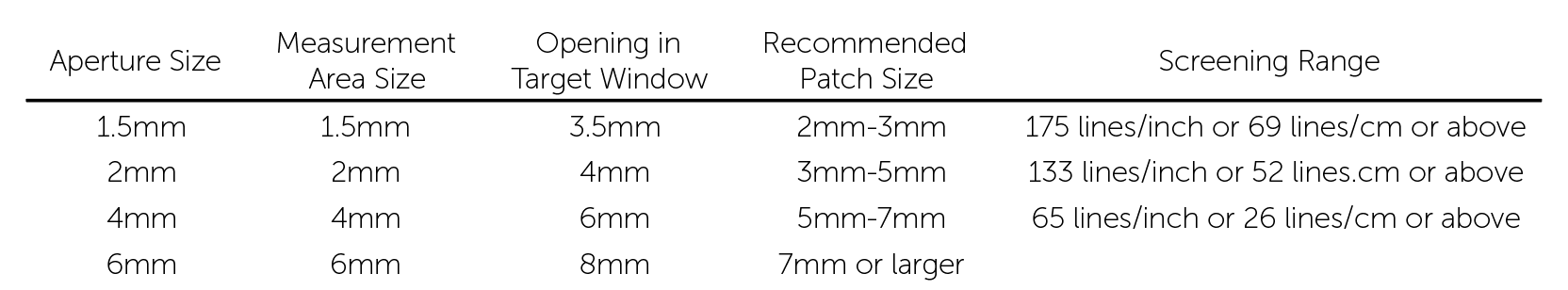
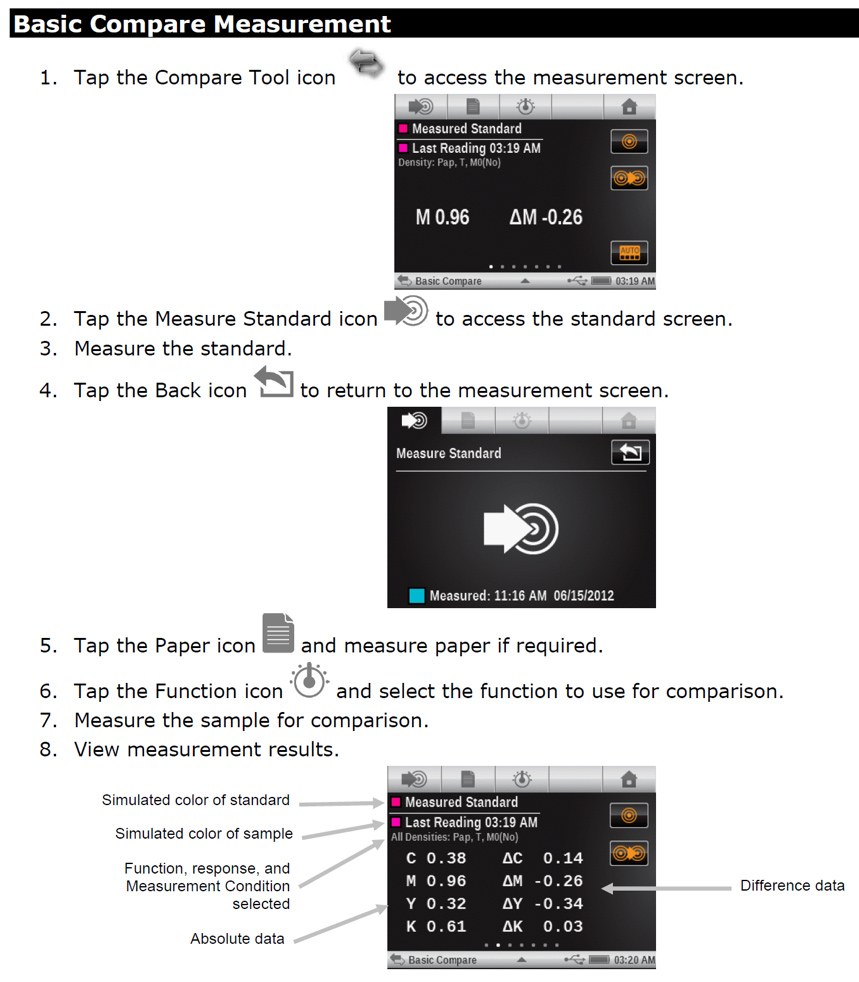
- Measuring Density
On the eXact menu screen, the Density function is located on the second page of the “Home” selections. Select “Basic Tool”, then tap the triangle icon at the bottom center of the screen to set the desired active functions.
- To take a measurement, place the aperture over the color patch, close the clam shell and wait for the beep. The reading will be displayed on the screen.
- Density Measurement Displays density values for the selected function and color.
- Select Density, Density Trend, or All Densities.
- Measure paper if required.
- Select color.
- Measure sample.
- View data.
Measuring for Neutral Density
If the goal is to measure neutral density for G7, the target densities will be defined based on the L*a*b* values of the target CRPC set.
- For example, to achieve a relative neutral density for the CRPC-6 2013 set, the following density values should be set as the target:
- K 25% target = 0.22 CMY Build 25% target = 0.25
- K 50% target = 0.49 CMY Build 50% target = 0.54
- K 75% target = 0.89 CMY Build 75% target = 0.91
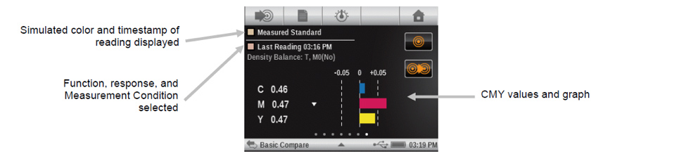
- Utilizing the CMY Balance function can help operators to achieve a neutral density when measuring CMY overprints.
- This feature allows the user to see if colors are balanced or dominant in the CMY tint blend.
- See the excerpt from the eXact manual.
CMY Balance Measurement
- Select CMY Balance function.
- Measure paper if required.
- Measure the grey balance standard.
- Measure sample.
- View data.
Measuring Dot Area / TVI
- In the Home menu area, select the Tone Value function
- Select the paper icon in the upper left hand corner to measure the base substrate.
- Place the eXact aperture on the non-printed area of the sample and measure to set the paper value.
- Measure the solid ink density (100%) of the ink color. This is used as a total value reference for the other dot percentages.
- Measure the tint values of the same ink color and record.
- Software is available to assist in recording density, dot values, and other data for each job for reporting/scorecarding and future reference.
- For more information, contact techteam@andvre.com.
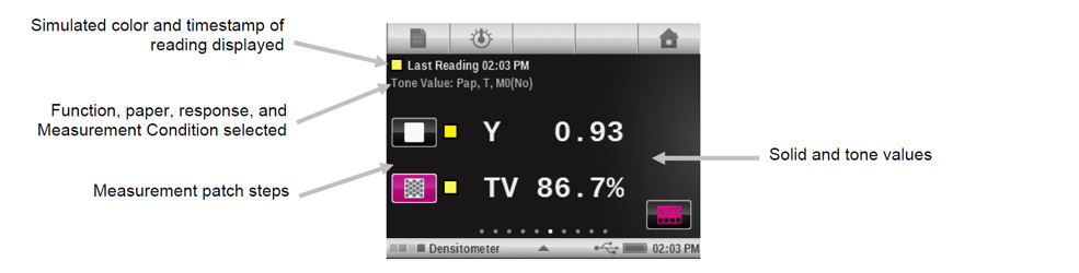
- See the image below for details on working with the eXact interface for dot area.
Tone Value (dot area) Measurement
-
- Displays tone value for the selected color. The procedure requires one solid and one tint measurement.
- Select Tone Value function.
- Select Color option if required.
- Measure paper. Once paper is measured, it is not required until there is a new substrate.
- Measure solid patch.
- Measure tint patch that corresponds to the measured solid.
- View tone value data for the tint patch.
- Continue with additional tint patches that correspond to the measured solid, or touch the solid patch on the left of the screen and measure another solid patch.
- Displays tone value for the selected color. The procedure requires one solid and one tint measurement.
Measuring Color Information (L*a*b*/Lch)
-
- To measure color information or measure the difference in color between 2 samples, it is required to have an eXact other than the Densitometer version.
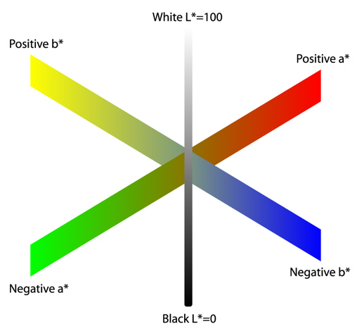
- In order to understand L*a*b* (or Lch) values, it is helpful to reference the color wheel below:
- To measure color information or measure the difference in color between 2 samples, it is required to have an eXact other than the Densitometer version.
-
-
- Each color will have a coordinate of 3 values. L*: Lightness, a*: the scale of green to red, and b*: the scale of yellow to blue.
- A target color will be communicated using these 3 values.
- For example, the L*a*b* values of a solid Cyan sample when targeting G7 with the CRPC-6 2013 should be:
- L = 56
- a = -37
- b = -50
- For example, the L*a*b* values of a solid Cyan sample when targeting G7 with the CRPC-6 2013 should be:
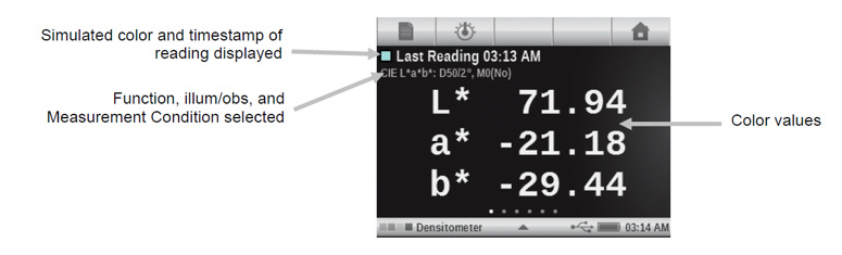
- On the eXact 2, the Colorimetric Measurement function is found and selected the same way as the Density function. On the second page of the “Home” selections. Select “Basic Tool”, then tap the triangle icon at the bottom center of the screen to set the desired active functions.
-
Colormetric Measurement
-
-
- Displays colorimetric measurement data for the selected function.
- Select L*a*b*, L*C*hº, XYZ or Yxy colorimetric function.
- Measure sample.
- View data.
-
Comparing 2 Colors
-
-
- It is very convenient on the eXact 2 to compare two different colors without saving any data.
-
Help Section
-
-
- Need more information? Here is a list of references and tools available to Xrite eXact and eXact 2 users:
- Online training is available for clients who purchase an eXact or eXact 2 device. Please see: http://www.xrite.com/xrite-eXact/training
- Check out the FREE tutorials about the eXact functionality.
- This site also contains Xrite certification programs.
- The training session “Going Beyond Density” a $159 value, is free with an eXact purchase.
- Updating Pantone Library
- The digital versions of the standard Pantone libraries are available for download for use with the eXact 2.
- Special libraries are available for purchase on the website.
- Calibration
- This device will calibrate periodically when needed. A notification will appear on screen to initiate the process. The with calibration plaque is included within the device – no more searching for the white/black chip/plaque!
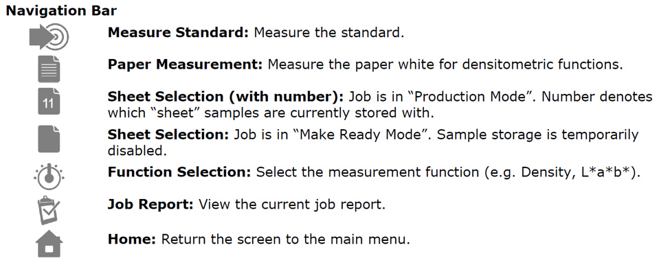
- Below is a chart identifying the icon functions on the Xrite eXact 2.
- Online training is available for clients who purchase an eXact or eXact 2 device. Please see: http://www.xrite.com/xrite-eXact/training
- Need more information? Here is a list of references and tools available to Xrite eXact and eXact 2 users:
-
Tech Tip 5- Calculating Flexographic Sheeted Polymer Distortion
There are a few things to know about distortion before we get into the numbers, things to consider.
-
-
- The repeat is driven by the gear or set dimension on a gearless press.
- Sticky back tape does not play a part in the distortion calculation.
- The calculation takes into account the stretch of the photopolymer only. The Mylar backing is excluded from the calculation. See image below.
-

The main component is to calculate your constant for .045, .067, .107 etc.… Once identified you can move to calculation of your distortion.
Distortion Calculations
Calculating the Constant
-
-
- Determine your amount of photopolymer, in this instance we will use a .067 plate. As shown in the illustration .062” x 2 as this is a function of the diameter, equaling 0.124”
- Take that value multiplied by pi (3.14159). 0.124 x 3.14159= .3895. This is your constant for 0.067 polymer. NOTE: 0.39 is a common and widely accepted value used in our industry.
-
Calculating the Distortion
-
-
- For this example we will use a 15” repeat. 15 – 0.3895 = 14.6105
- 14.6105 / 15 = 0.97403 – or – 97.403%
-
Another way to calculate without using the constant
-
-
- 15 / 3.14159 = 4.7747
- Subtract your polymer thickness from the Print diameter 4.7747 – .124 = 4.6507
- 4.6507 / 4.7747 = 0.974029 – or 97.403%
-
If you have questions please reach out to our Tech Team at techsupport@andvre.com
Download Tech Tip 5- Calculating Flexographic Sheeted Polymer Distortion